Flash

G for genious

Friday, February 1, 2013

Power Factor


Power factor is characteristic of alternating current (AC) circuits. Always a value between (0.0) and (1.0), the higher the number the greater/better the power factor.

Circuits containing only heating elements (filament lamps, strip heaters, cooking stoves, etc.) have a power factor of 1.0. Other circuits containing inductive or capacitive elements (ballasts, motors, personal computer, etc.) usually have a power factor below 1.0.

Normal power factor ballasts (NPF) typically have a value of (0.4) - (0.6). Ballasts With a power factor greater than (0.9) are considered high power factor ballasts (HPF).

The significance of power factor lies in the fact that utility companies supply customers with volt-amperes, but bill them for watts.

The relationship is (watts = volts x amperes x power factor). It is clear that power factors below 1.0 Require a utility to generate more than the minimum volt-amperes necessary to supply the power (watts).
This increases generation and transmission costs. Good power factor is considered to be greater than 0.85 or 85%.

Utilities may impose penalties on customers who do not have good power factors on their overall buildings.

Watts, or real power, is what a customer pays for. VARS is the extra “power” transmitted to compensate for a power factor less than 1.0. The combination of the two is called "apparent" power (VA or volt-amperes).

Consider this popular analogy to clarify the relationship between real and apparent power.

We all know a glass of draft beer generally has a "head" on it. Let's say your favourite pub institutes a new policy - you only pay for the beer, not the foam. While the foam is just aerated beer, it is not really usable in that form.

If the glass of beer is half foam, you pay half the price.

This is the same principle as electricity generation - the consumer only pays for the beer (real power), not the foam
(The "VARS" mentioned above).
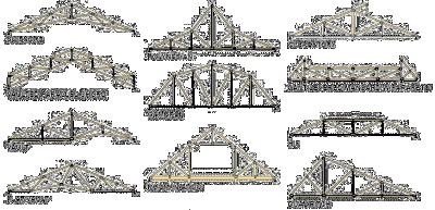

Truss

In architecture a truss is a structure comprising one or more triangular units constructed with straight members whose ends are connected at joints referred to as nodes. External forces and reactions to those forces are considered to act only at the nodes and result in forces in the members which are either tensile or compressible forces. Moments (torques) are explicitly excluded because, and only because, all the joints in a truss are treated as re volute.

A planar truss is one where all the members and nodes lie within a two dimensional plane, while a space truss has members and nodes extending into three dimensions. The top beams in a truss are called top chords and are generally in compression, the bottom beams are called bottom chords and are generally in tension, the interior beams are called webs, and the areas inside the webs are called panels

Thursday, January 24, 2013

35 Overs Cricket Match?????? If not 50 or 20, what about 35?

Cricket is not perfect, neither would we want it to be. Match-ups are as likely to be exasperating as exhilarating. Fifty-over cricket has taken it in the neck for being out of date. "You're obsolete my baby / My poor old-fashioned baby / I said baby, baby, baby you're out of time" wrote Jagger and Richards, and T20 is the flared trouser of the day.
But T20 is not cricket in the true sense. T20 has escape clauses that allow mediocre talent to survive. Worse still, the best talent is in the wash with everyone else, restricted by overs and playing regulations that dumb down a greater game.
If - and I say if because I'm not convinced yet - cricket is indeed cannibalising itself, 35 overs is a way to go. There is just enough time to be bowled out, which is crucial to the fabric of the sport, and not quite enough time to throttle back during the predictable middle overs. Maybe you play with two new balls and have a first 15-over period where, say, three fielders have to be in an attacking position and only three can be outside the 30-yard ring. After that you resort to the regulations of T20 as we know them. Urgency but not disrespect: the best of both worlds perhaps?

Tuesday, January 22, 2013

Simple Gas Turbine Cycle


A schematic diagram of a simple gas turbine power plant is shown in figure. Air is drawn from the atmosphere into the compressor, where it is compressed reversibly and adiabatically. The relatively high pressure is then used in burning the fuel in the combustion chamber. The air fuel ratio is quite high (about 60:1) to limit the temperature of the burnt gases entering the turbine. The gases then expand isentropically in the turbine. A portion of the work obtained from the turbine is utilized to drive the compressor and the auxiliary drive, and rest of the power output is the net power of the gas turbine plant.

A gas turbine plant works using a Brayton or joule cycle. This cycle was originated by joule, a British engineer for use in a hot air reciprocating engine and later in about 1870 an American engineer George Brayton tried this cycle in a gas turbine. This cycle consists of two constant pressures and two adiabatic processes. The P-V and T-S diagrams of the cycle are as shown in figure.


Process 1 – 2: isentropic compression in the compressor

Process 2 – 3: constant pressure heat addition in the combustion chamber

Process 3 – 4: isentropic expansion in the turbine

Process 4 -1: constant pressure heat rejection in the atmosphere or cooling of air in the intercooler (closed cycle).